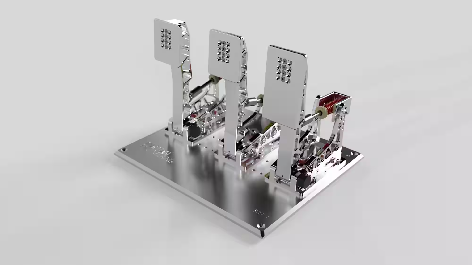
Custom Sim Racing Pedals - ME1
A CNC-machined pedal set, combining hardware, sensing, and embedded control for sim racing.
Problem
Sim racing hardware can be expensive, and load-cell-based pedal systems were far beyond my budget. To achieve the accuracy and realism I was looking for, I chose to design and build a custom set.
Goal
Design and build a cost-effective, high-performance pedal set with realistic feedback, durability, and long-term serviceability.
Approach
Initial Concept
The work started with research and requirements definition. Most commercial pedals rely on folded sheet metal, but a CNC-machined design provides superior stiffness, precision, and a distinctive visual identity.
Sensor selection guided the mechanical layout. The brake uses a load cell for force-based measurement, delivering a more realistic feel than potentiometer-based position sensing. The throttle and clutch use hall-effect sensors for contactless, high-precision position feedback.
Early iterations explored a bold, recognizable silhouette and established the overall packaging.
Piston Support Iteration
One early concept used a fork-style piston support. During pedal travel the piston axis changes, requiring rotation that the fixed fork could not accommodate. The resulting bending moment on the fork would also introduce long-term fatigue risk.
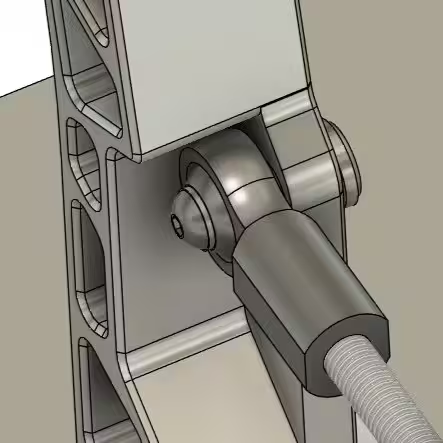
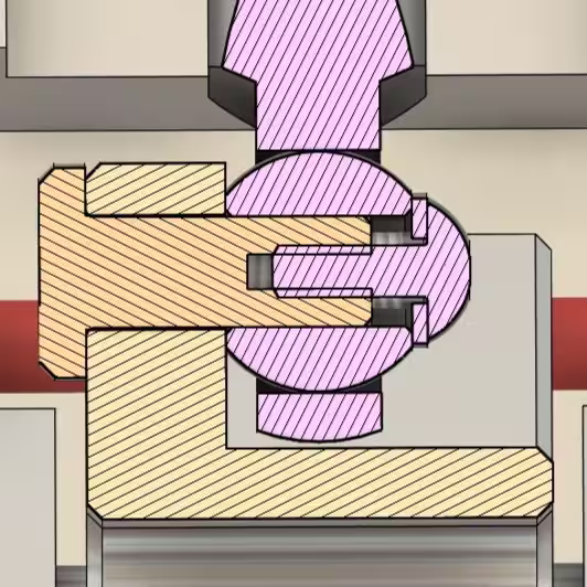
The ball-joint mounting in that layout also complicated machining. I replaced the dual-sided support with a single-sided, asymmetric arm and designed a custom clevis pin with an axial threaded blind hole. This allows the pin to clamp tightly, minimizing play and distributing load more evenly across the joint.
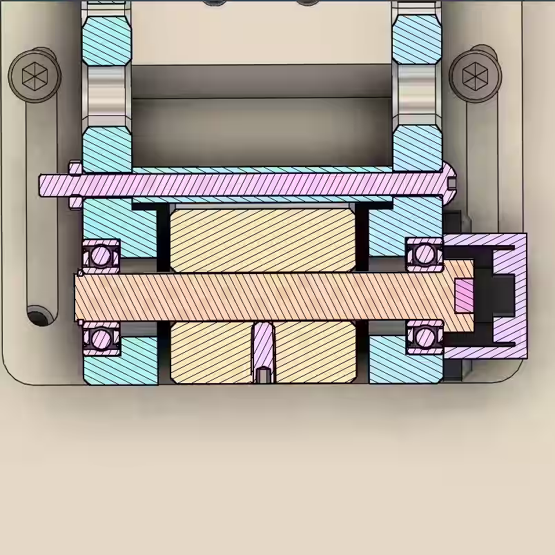
Rotational Axis and Sensing
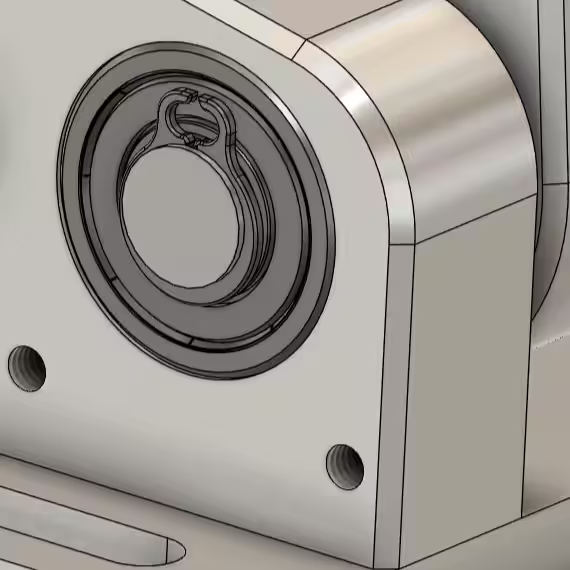
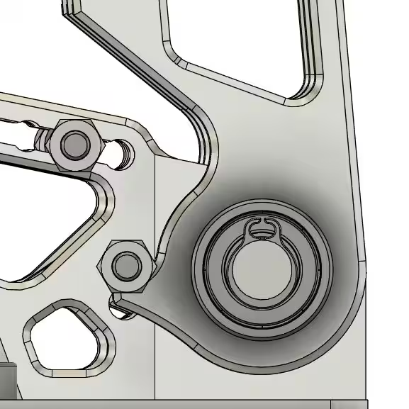
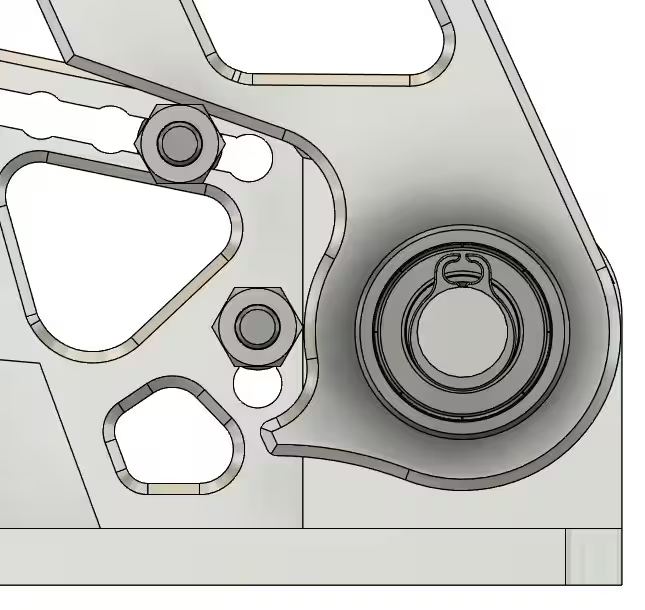
The rotational axis of the pedal arms was also revised. Instead of pressing bearings into the arms, the bearings are now located in the side plates. A rigid shaft is fixed to the arm, and a set screw secures it with tight tolerances. Axial retention is provided by the clevis pin head on one side and a Seeger ring on the other.
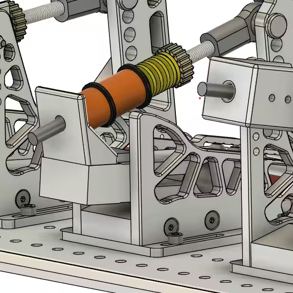
Throttle and clutch rotation is measured with hall-effect sensors. A diagonally magnetized neodymium magnet is seated in a pocket machined into the shaft head. The AS5600 sensor is mounted in a small 3D-printed housing, positioned roughly 1 mm from the magnet to maintain a precise air gap.
Adjustable Endstops
Endstop design was another focus area. The pedal arm was updated to include defined start and end surfaces, and the side plates provide multiple mounting positions for simple adjustability. The starting endstop can be set between two positions, while the final endstop has five adjustment points.
Starting and final positions:
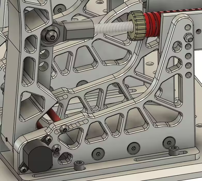
Brake Assembly
Brake side plates are designed differently because they do not require the upper through-holes. The piston support is mounted directly to the load cell, which must be loaded in compression to measure force accurately.
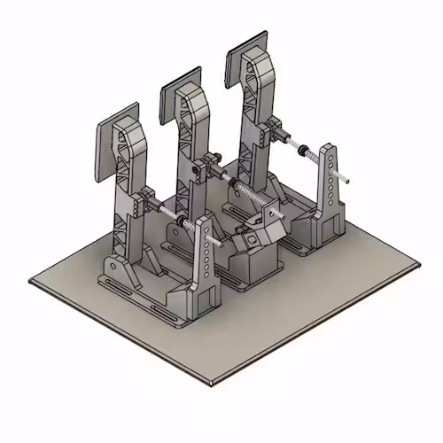
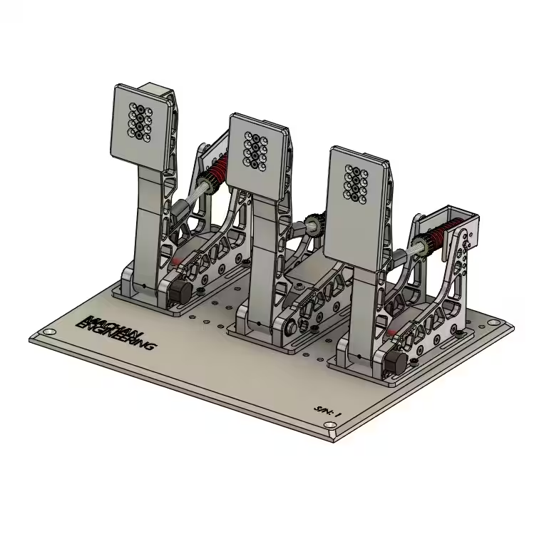
Final Assembly
These iterations resulted in a robust, adjustable mechanical platform, shown below.
Current state
The mechanical parts are nearly complete, with a few minor turned components still pending. Electronics development, primarily the PCB, will begin after final mechanical assembly. Firmware and software development will follow the electronics phase.